Dev Blog #60
Hello, comrades!
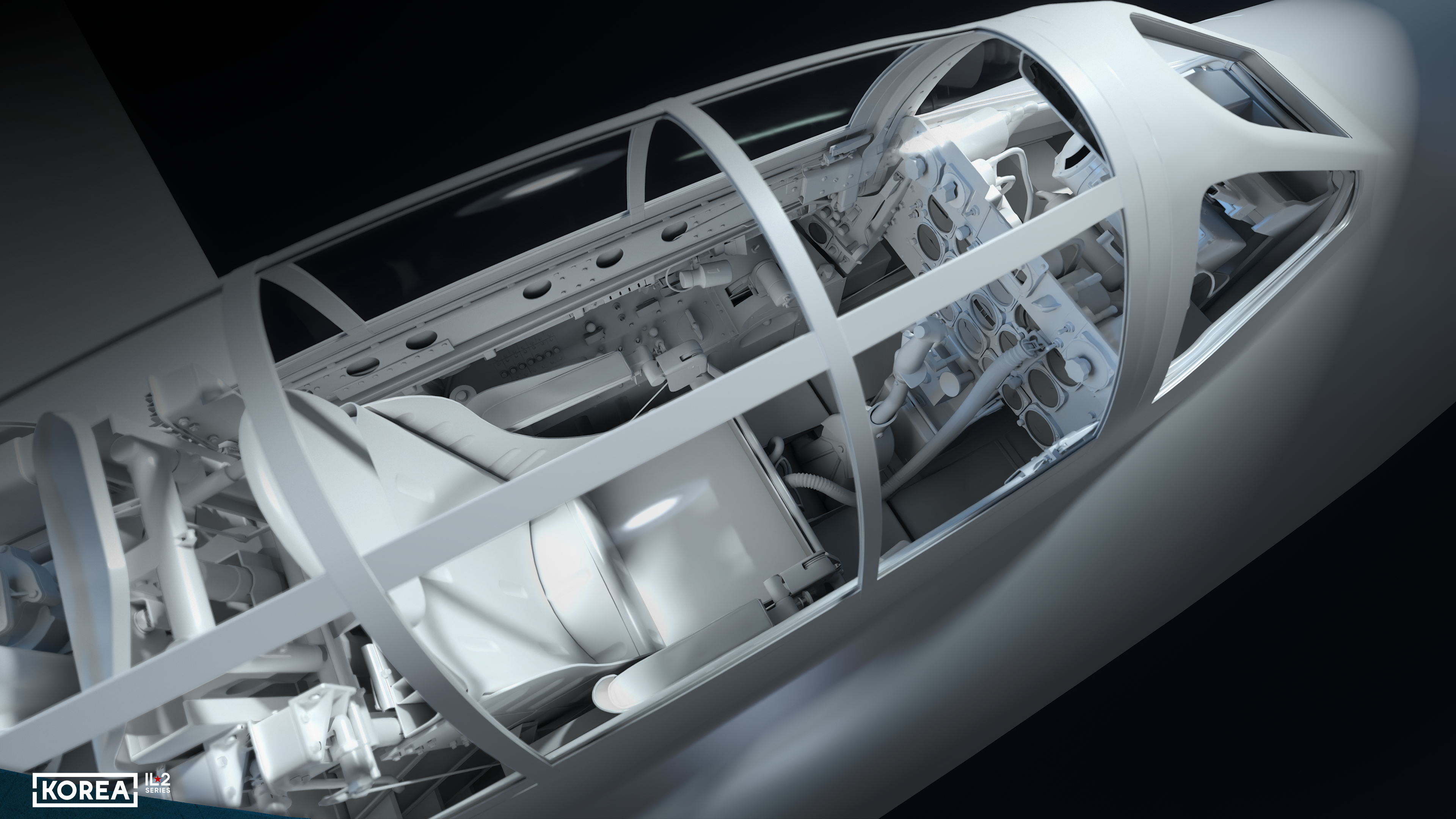
The closer we get to the official release date of our new simulator, the less work remains to be done. As you may have noticed from previous publications, almost all aircraft cockpits are ready, with only one remaining — and that is the one we will discuss in detail today in our 60th dev blog. This is the cockpit of the F-84E Thunderjet.
The closer we get to the official release date of our new simulator, the less work remains to be done. As you may have noticed from previous publications, almost all aircraft cockpits are ready, with only one remaining — and that is the one we will discuss in detail today in our 60th dev blog. This is the cockpit of the F-84E Thunderjet.
This aircraft had a complicated history, which we already discussed in the 43rd dev blog. The prototype took to the skies after World War II and, unlike the F-80 Shooting Star, had a rich array of instruments. In terms of cockpit equipment, the Thunderjet can rival the F-86 Sabre, as you can see in the images of the cockpit we have lovingly recreated for you in Korea. IL2 Series.
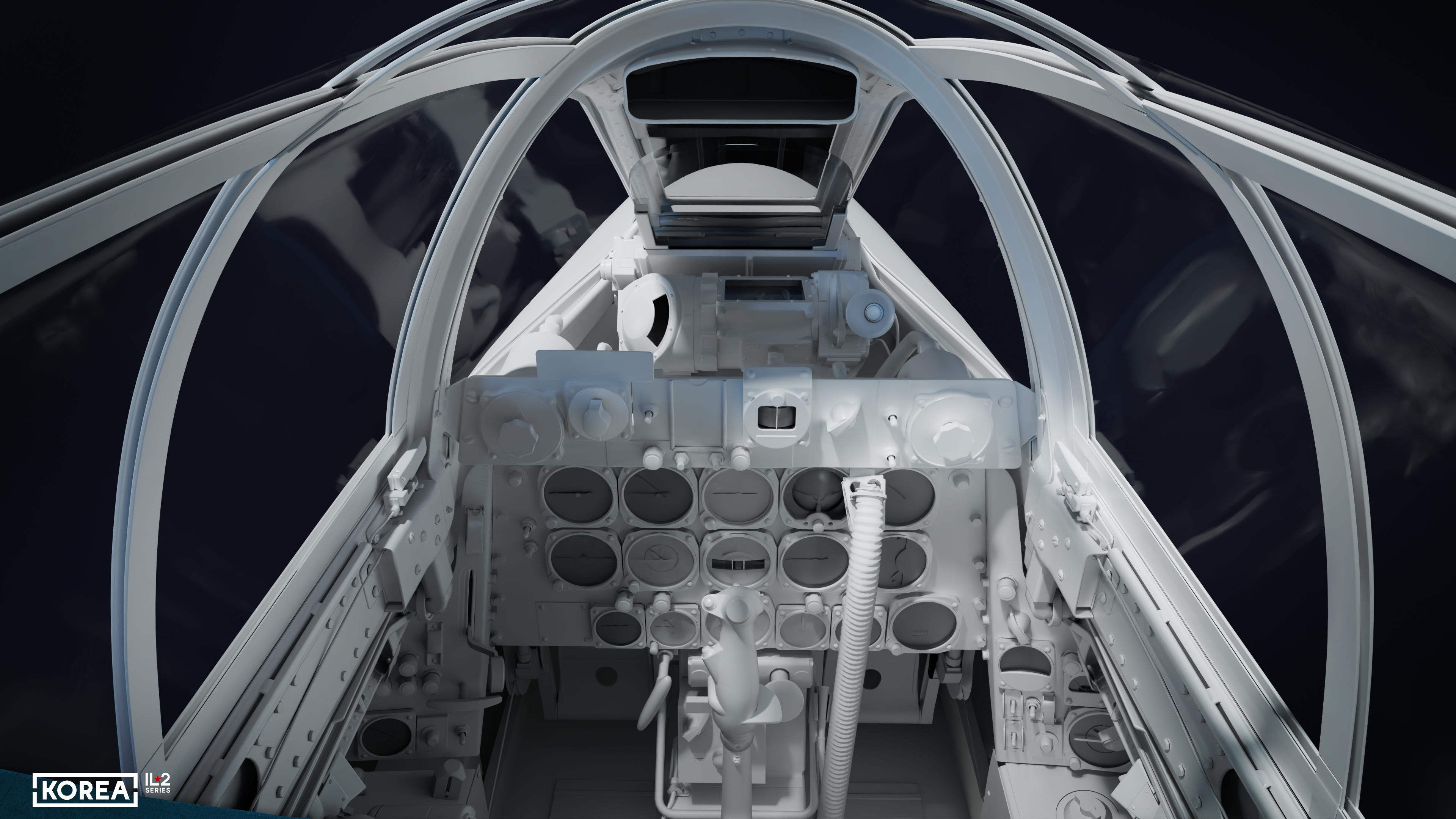
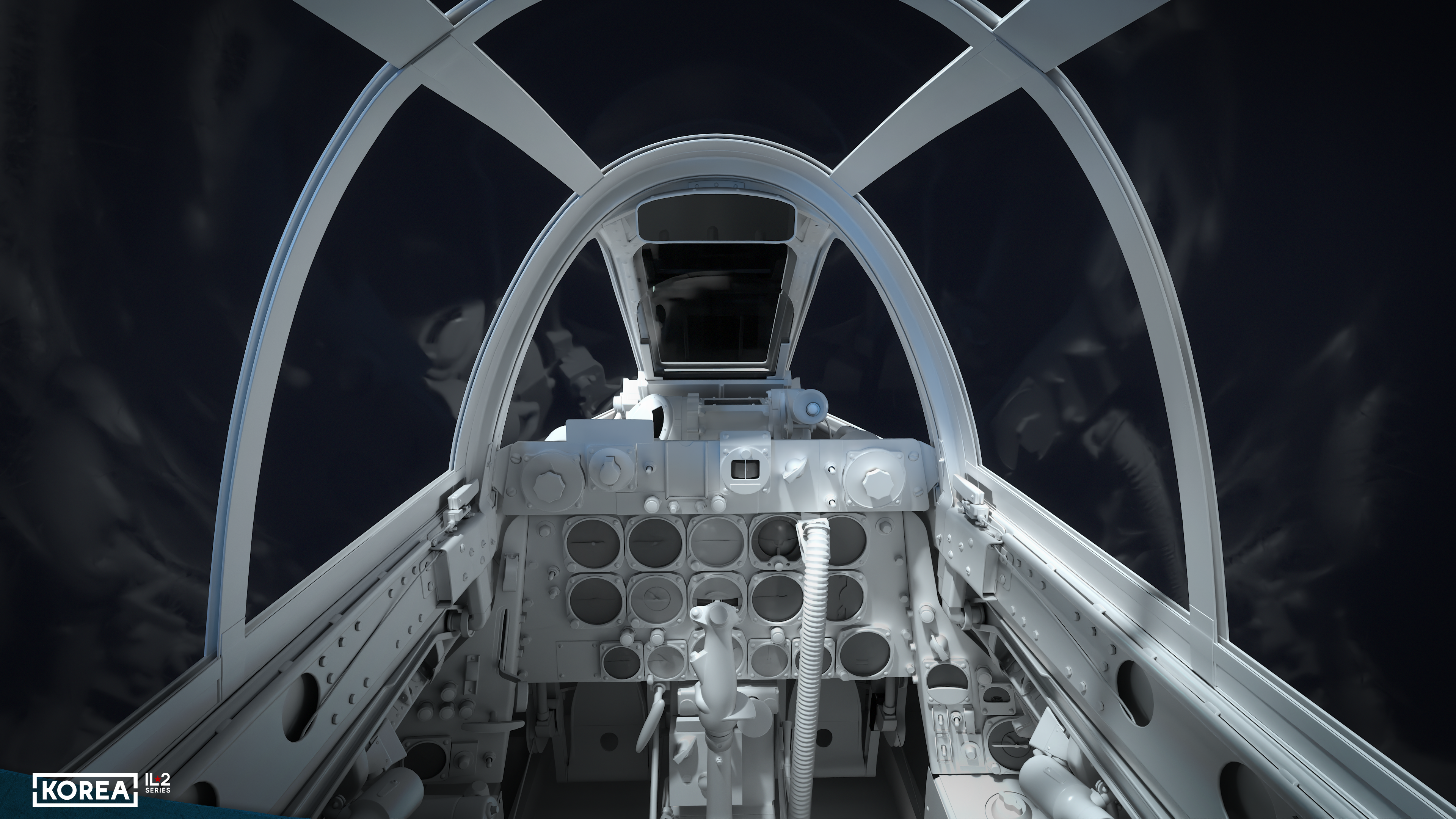
Let’s start our review with the central part — an A-1CM gyroscopic sight is installed in front of and above the instrument panel. Unlike the same sight on the Sabre (where armored glass acts as a reflector), here it has a dedicated reflector. The sight is coupled with an AN/APG-30 radar rangefinder, which at high altitudes is capable of automatically determining the range to the target observed in the sight and setting that range in the sight. To the right of the sight is a red signal lamp that flashes until the target is detected and the reflected radar signal is received; once the range is determined, it begins to glow continuously. The radar rangefinder control button is located on the B-8 aircraft control stick, which was standard for that period.
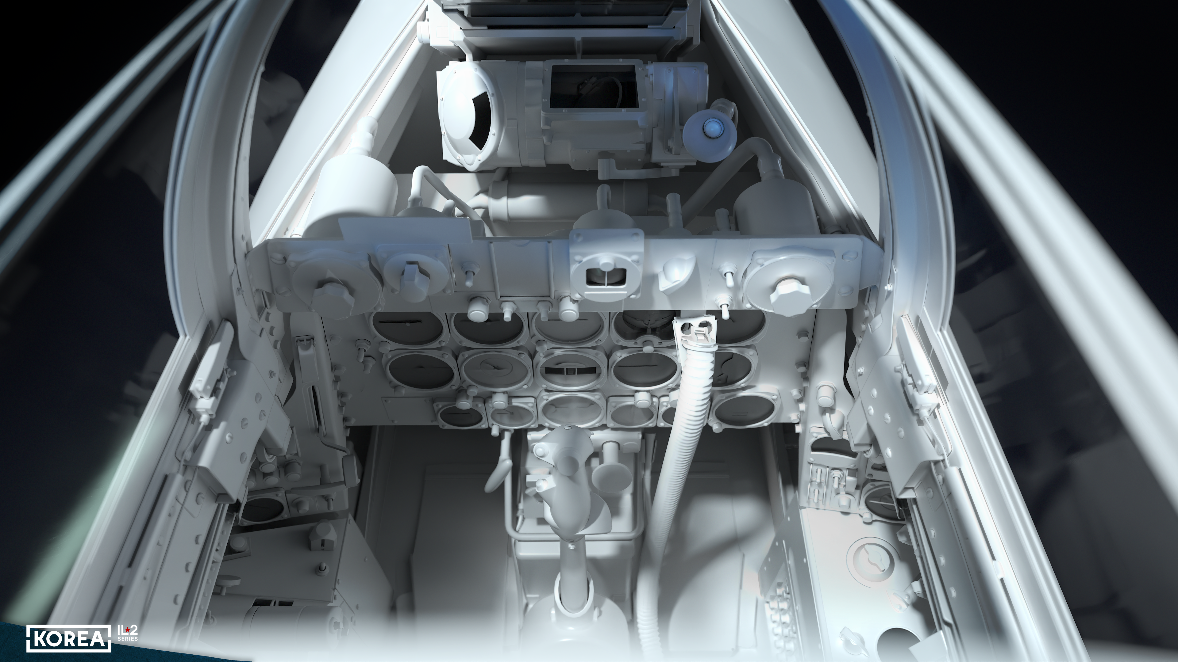
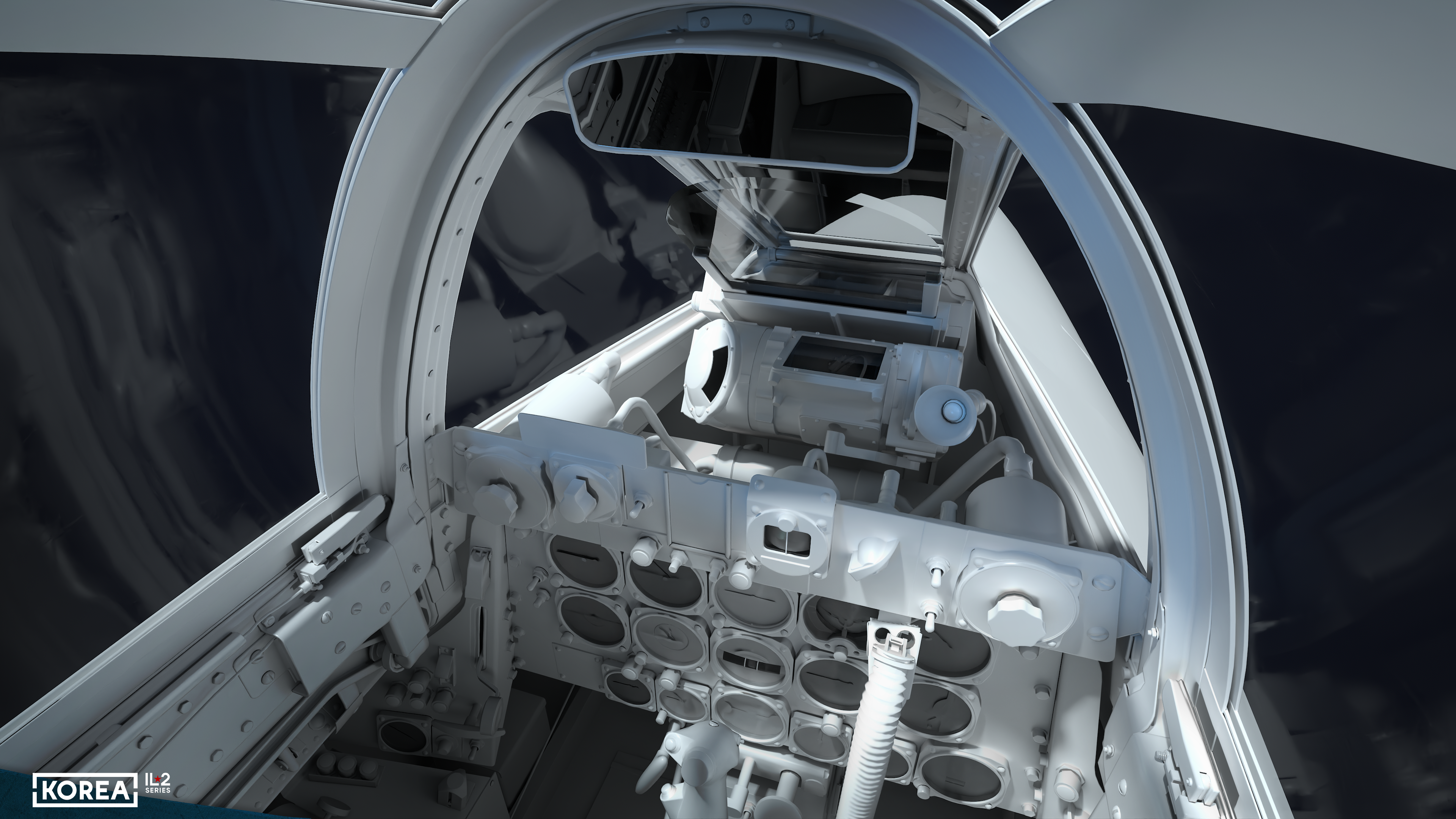
The central instrument panel has a raised upper section, or "balcony," that primarily houses the sight controls. The main part of the central panel contained three rows of instruments. The top row includes an accelerometer, a speed indicator, a gyrocompass indicator, a gyroscopic artificial horizon, and an engine speed indicator. There are radio compass, altitude, turn, vertical speed, and nozzle gas temperature indicators in the second row. The third row holds the instruments for monitoring the engine systems (fuel and oil). Below the central panel is the A-3 control panel for setting the launch intervals and salvos of the rockets.
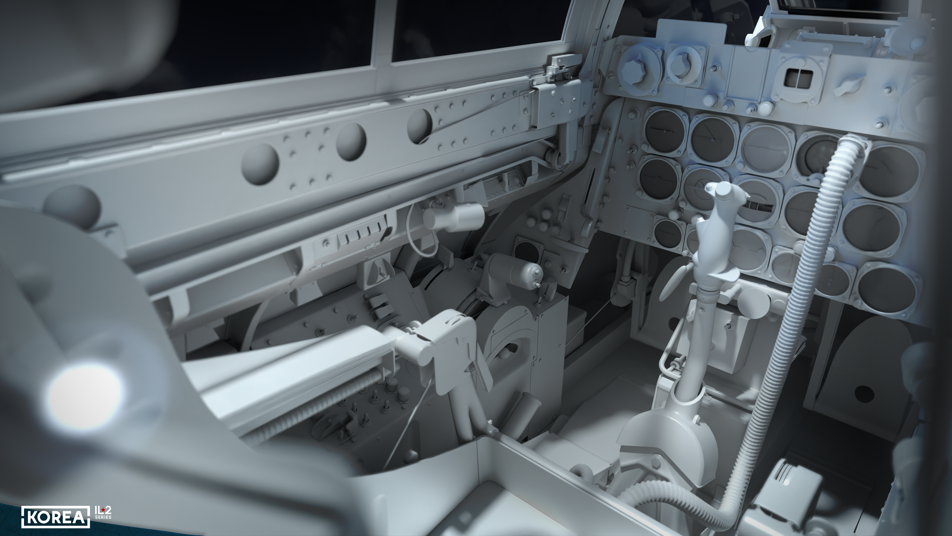
To the left of the central panel are the landing gear and flap position indicators, as well as the landing gear release handle and the landing light switch. To the right are the aircraft electrical system indicators. The left console (on the left side) houses the weapons control unit; closer to the pilot is the fuel system control unit; behind it is the fuse block; and in front is the engine control lever, which has buttons for locking the sight and radio communication. The engine control lever can rotate around its axis (like on a motorcycle) to manually set the sight range. Under the left console is a large handle for the hydraulic system’s hand pump, and on the console’s side is its switch.
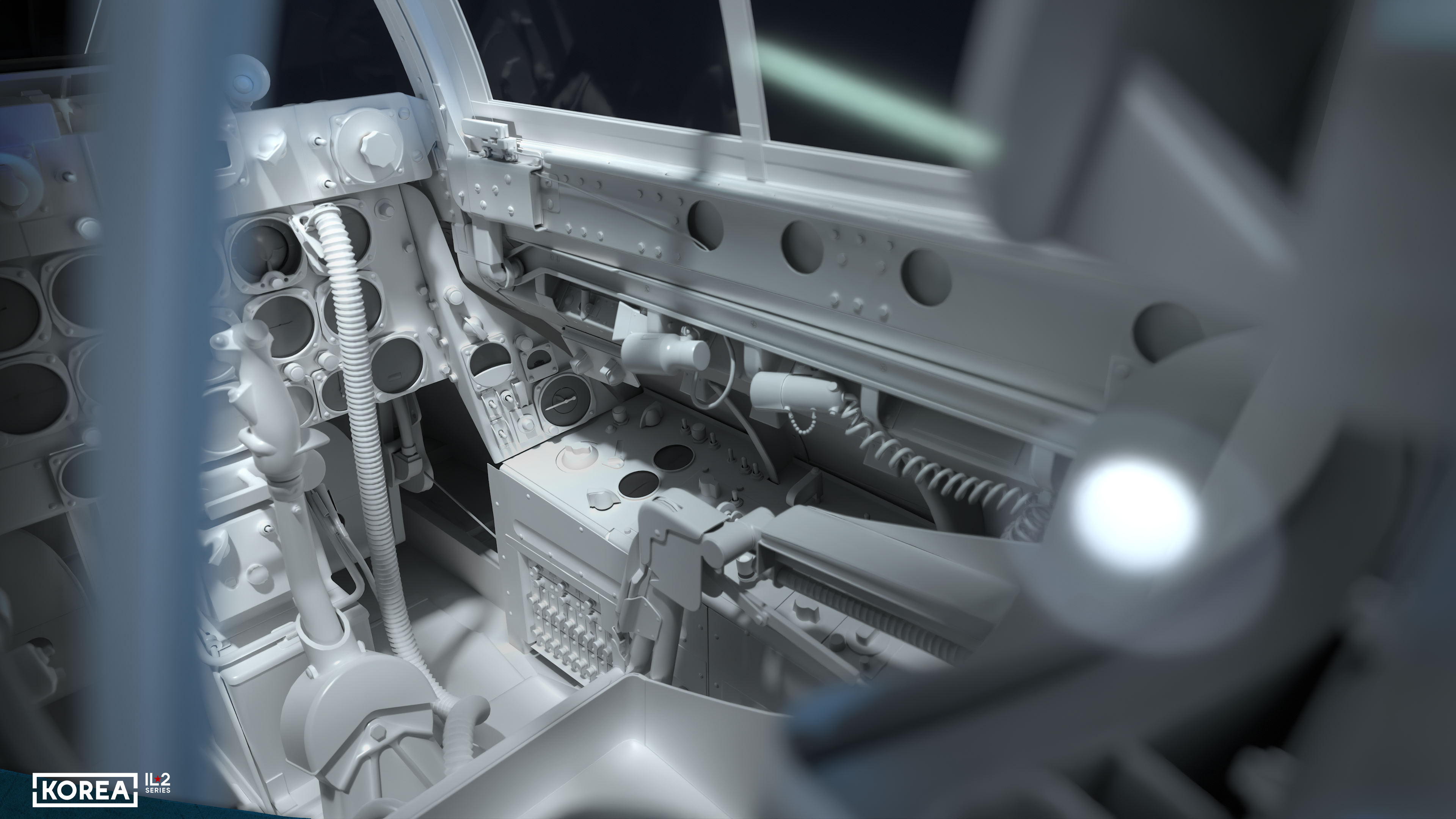
The right console (on the right side) in the front section houses the oxygen system controls and indicators, followed by the radio compass unit and the light controls above it. The rear section of the console houses the radio set and the friend-or-foe radio transponder control units. At the bottom of the console’s side surface is a fuse block. Under the guides of the sliding part of the cockpit canopy, on the left and right sides, you can see three modular lighting lamps. The two front ones are ultraviolet, and the one with a telephone wire is a repositionable floodlight with a red filter.
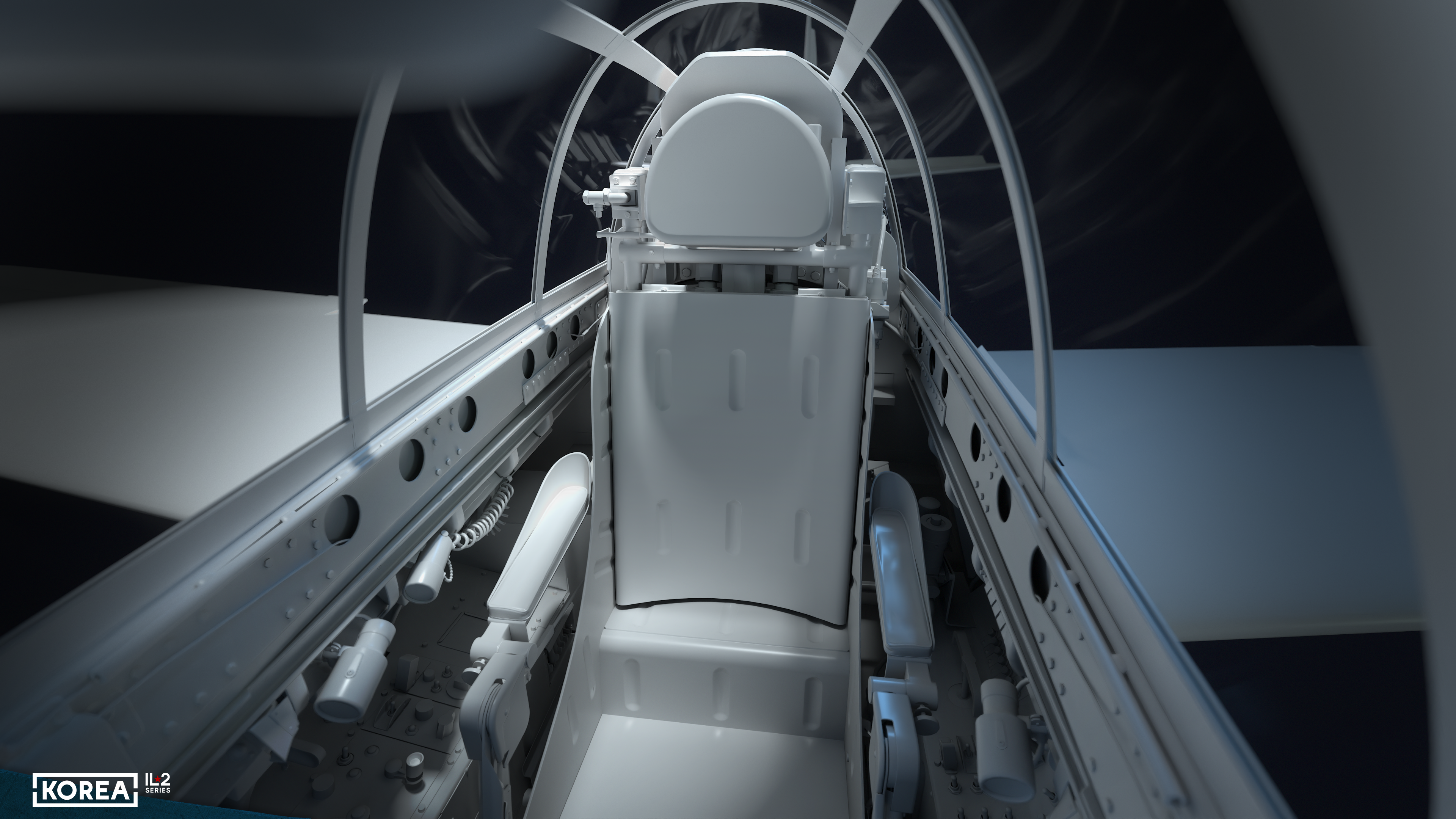
The aircraft is equipped with a catapult of the builder’s design — the era of Martin-Baker's dominance in the ejection seat market had not yet arrived. On the left, in front of the armrest, there is a handle for tightening the seat belts, and on the right, a handle for releasing and activating the catapult safety catch. The back of the ejection seat has a distinctive, clearly visible recess for the pilot’s parachute, and the seat bowl has a recess for a bag containing an inflatable life raft.
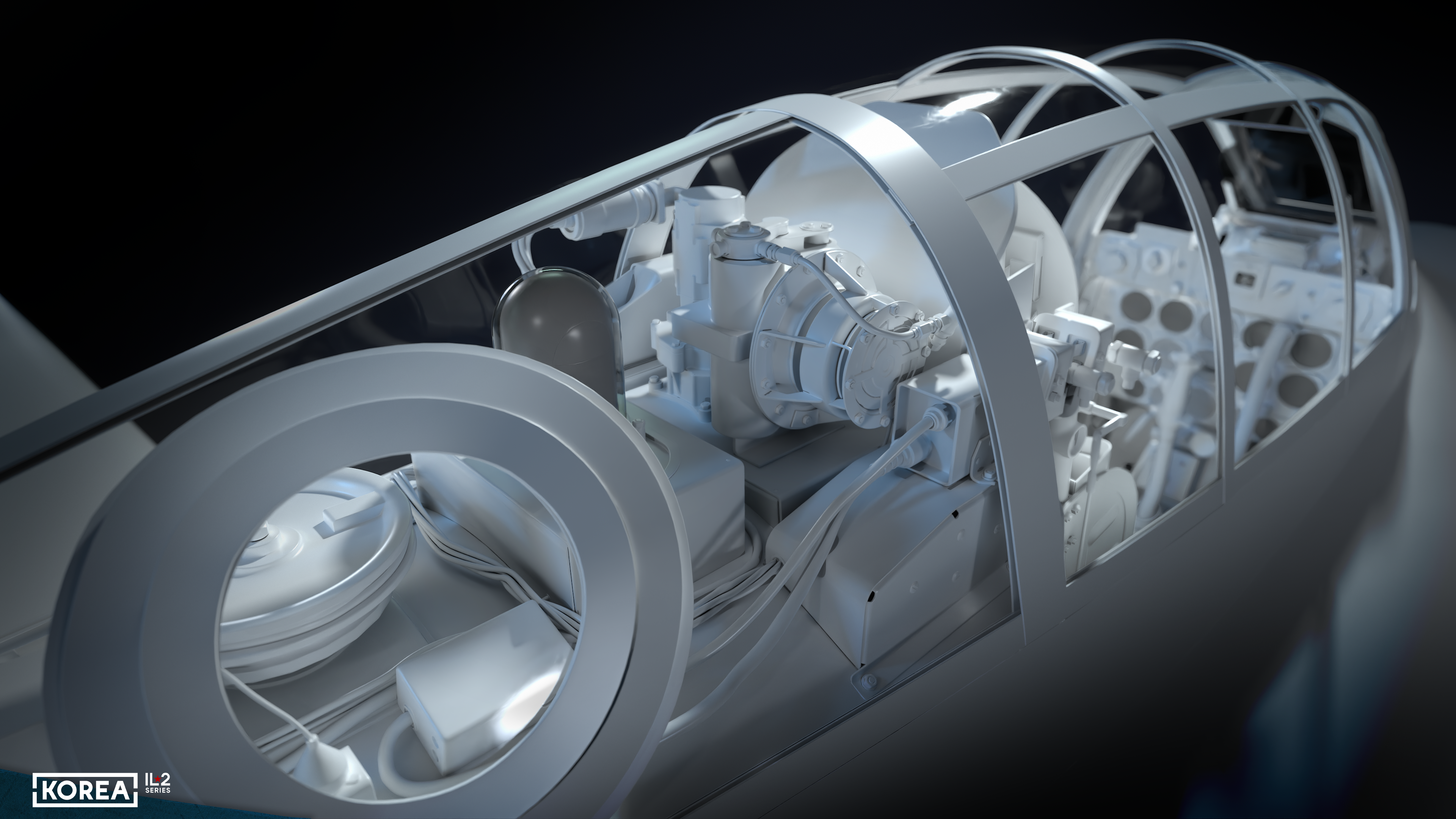
Behind the ejection seat is a rather massive armored backrest with an inclined armored headrest. Behind the backrest are the cockpit pressurization unit and a transparent cup for the rotating radio compass antenna, which is accessed through a round hatch in the canopy glazing. Further back is the pulley for the wiring tensioner of the opening part of the canopy. At the very rear of the cockpit canopy is the upper fuselage navigation light.
In the game, all the instrumentation in the aircraft cockpits will be described in detail and shown in the Museum game mode. Until then, when the game is released, we will continue to tell you in detail how the aircraft in our game are designed and what their history is. We are also eagerly awaiting seeing this cockpit in all its glory ourselves, with textures: color always transforms a model beyond recognition, in this case, the cockpit, where you will spend most of the playing time.